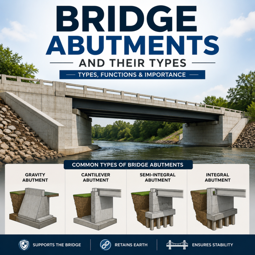
Bridge abutments sit at both ends of a bridge, carrying the deck’s load down into the ground while holding back the approach embankment behind them. Get the abutment type wrong and you’re looking at cracked approach pavements, stuck expansion joints, or a maintenance headache for the next fifty years. Get it right, and it can be one of the more economical parts of the whole structure.
For engineers, students, and contractors working under AASHTO LRFD and FHWA guidance in the United States, there isn’t just one way to classify abutments. State DOTs typically look at them through three different lenses: how the abutment resists load structurally, where it sits relative to the embankment, and how it handles thermal movement at the bridge deck. This guide walks through all three so you can see how the pieces fit together, and how to think about picking the right one for a given site.
What Does a Bridge Abutment Actually Do?
Here are the major purposes of Bridge Abutment
– Transfers vertical loads (dead load, live load) from the superstructure into the foundation soil or rock
– Resists lateral earth pressure from the retained embankment behind it
– Absorbs longitudinal forces from braking, thermal expansion/contraction, and, in seismic zones, ground motion
– Provides a smooth transition between the roadway and the bridge deck via the approach slab
Classification by Structural Behavior
This is close to the classification FHWA uses in its own LRFD design examples: cantilever, gravity, counterfort, MSE, stub/semi-stub, spill-through, and integral/semi-integral all appear on the same list. Grouping them by how they resist force makes the differences easier to see.
-
Gravity Abutments
Gravity abutments rely purely on the mass of the abutment itself — usually plain or lightly reinforced concrete or stone masonry — to resist overturning and sliding from the earth pressure behind it. There’s no significant reinforcement doing structural work; the wall is simply heavy enough to stay put.
Best for: short-to-medium span bridges, low abutment heights, sites where concrete is cheap relative to labor and reinforcement
Downsides: needs a lot of material, and doesn’t scale well as height increases — the concrete volume grows fast
-
Cantilever (Reinforced Concrete) Abutments
A cantilever abutment is essentially a cantilever retaining wall doing double duty as a bridge support: a vertical stem, a footing, and reinforcing steel that let the wall resist overturning through bending rather than sheer bulk. Because reinforcement carries the moment, the concrete section can be much thinner than a gravity abutment of the same height.
– Best for: medium-height abutments where a gravity section would be excessively bulky
– Downsides: more design and detailing effort than a gravity wall; formwork is more complex
-
Counterfort Abutments
Once a cantilever abutment gets tall enough, the stem and footing see bending moments large enough to need extra help. Counterfort abutments add triangular concrete ribs (counterforts) tying the stem back to the footing, which stiffens the wall and cuts down on reinforcement and stem thickness.
– Best for: tall abutments (roughly 20+ ft), where a plain cantilever section becomes impractical
– Downsides: formwork and rebar detailing around the counterforts add construction cost and time
-
Mechanically Stabilized Earth (MSE) and Geosynthetic Reinforced Soil (GRS) Abutments
Instead of a single rigid concrete wall, MSE abutments build up the embankment using layers of compacted fill reinforced with steel strips, welded wire, or geosynthetic grids, faced with modular panels or blocks. GRS abutments — and FHWA’s GRS-IBS (Geosynthetic Reinforced Soil–Integrated Bridge System) in particular — take this further, alternating closely spaced geosynthetic reinforcement with compacted aggregate directly under the bridge seat, often eliminating the need for a separate footing or bearing.
FHWA has documented GRS-IBS use on several hundred bridges nationwide, mostly on lower-volume routes, because it can be built faster and at lower cost than a conventional pile-supported abutment.
–Best for: sites with modest loads, tight construction schedules, lower-volume roads, and projects prioritizing lower long-term cost
– Downsides: less design history than conventional concrete abutments for high-volume, high-load bridges; settlement behavior needs careful geotechnical characterization
Classification by Position Relative to the Embankment
State bridge manuals (Wisconsin DOT, Connecticut DOT, and others) also classify abutments by where they physically sit relative to the approach fill — a decision that’s really about balancing span length against substructure cost.
-
-
Full-Height (Closed) Abutments
A full-height abutment sits at the toe of the embankment and retains the entire height of fill behind it, essentially functioning as a tall retaining wall. It keeps span length as short as possible, but that means more concrete, more retained earth pressure, and a larger structure overall.
– Best for: urban or space-constrained sites where minimizing bridge length matters more than substructure cost
– Downsides: highest material cost among the position-based types; more exposed to vehicle impact in underpass situations
-
Stub (Perched/Shelf) Abutments
A stub abutment sits at or near the top of the embankment slope, with fill sloping away in front of it. It’s shorter and lighter than a full-height abutment, but the trade-off is a longer overall span, since the abutment has moved back from the obstruction being crossed.
-Best for: most modern highway bridges — it’s frequently the default choice in state DOT manuals because it also minimizes long-term approach settlement problems
-
– Downsides: longer spans increase superstructure cost, which can offset the abutment savings
-
Semi-Stub Abutments
A semi-stub abutment splits the difference, sitting partway down the embankment slope between a full-height and a stub abutment. It’s a middle-ground option when neither extreme fits the site geometry well.
– Best for: sites where a full stub abutment would create too long a span but a full-height abutment isn’t justified
– Downsides: less standardized than stub or full-height designs, so detailing is often more site-specific
-
Spill-Through (Open) Abutments
Instead of a single wall retaining the full embankment, a spill-through abutment uses columns or a frame bearing on a footing set into the slope, with the embankment fill “spilling through” to rest against the columns at its natural angle of repose. It’s a common choice for waterway crossings because it keeps the channel relatively open.
– Best for: bridges over streams and floodplains where hydraulic capacity matters, and sites where future widening (adding spans) is anticipated
– Downsides: more exposed to slope erosion and scour around the columns; often needs riprap protection at the toe.
| Type | Primary Driver | Typical Use Case |
|---|---|---|
| Gravity | Self-weight | Short spans, low walls |
| Cantilever | Reinforced bending | Medium-height walls |
| Counterfort | Reinforced bending + ribs | Tall walls (20+ ft) |
| MSE / GRS | Reinforced soil mass | Lower-volume roads, tight budgets |
| Full-height | Minimizing span length | Urban, space-constrained sites |
| Stub | Minimizing substructure size | Default choice on most highways |
| Semi-stub | Balance of span vs. wall size | In-between site geometry |
| Spill-through | Hydraulic openness | Waterway crossings |
Factors That Actually Drive the Decision
In practice, bridge engineers rarely pick a type off a menu — the site tells them what’s workable. The main factors are:
Span length and bridge geometry – longer spans push toward stub or integral abutments to control cost
Soil and foundation conditions – poor soil may rule out MSE/GRS options or push the design toward deep foundations
Skew angle – high skew complicates integral abutment behavior and is a hard limit in many state manuals
Hydraulics – waterway crossings often favor spill-through abutments for channel capacity and scour behavior
Maintenance budget – agencies increasingly default to integral or semi-integral abutments specifically to cut long-term joint maintenance
Construction schedule and budget – MSE/GRS options can shorten construction time significantly on lower-volume routes
Seismic zone – abutment-to-superstructure connection details change substantially in high-seismic regions
Read Also-
Cantilever Bridges – Advantages, Disadvantages, and Examples
OSHA Field Safety and Health Manual
Final Thoughts
There’s no single “best” bridge abutment — only the one that fits a given span, site, soil, and budget. Understanding all three classification systems (structural behavior, embankment position, and joint behavior) is what lets an engineer talk through trade-offs with a client or reviewing agency instead of defaulting to whatever was used on the last job. For students, it’s also the fastest way to make sense of why state DOT manuals list so many abutment names for what is, structurally, a fairly small set of underlying ideas.
References
-
Federal Highway Administration. Abutment and Wingwall Design Example (LRFD). FHWA Bridges & Structures. https://www.fhwa.dot.gov/bridge/lrfd/fc_8.cfm
-
Federal Highway Administration. Design and Construction Guidelines for Geosynthetic Reinforced Soil Abutments and Integrated Bridge Systems, Publication No. FHWA-HRT-17-080 (2018). https://www.fhwa.dot.gov/publications/research/infrastructure/structures/bridge/17080/17080.pdf
-
Connecticut Department of Transportation. Bridge Design Manual, Section 5: Abutments, Piers, and Walls. https://portal.ct.gov/-/media/dot/bridge-design/publications/manual-sections/section-05–abutments-piers-and-walls.pdf
-
Wisconsin Department of Transportation. Bridge Manual, Chapter 12: Abutments (July 2024). https://wisconsindot.gov/dtsdManuals/strct/manuals/bridge/ch12.pdf
-
New York State Department of Transportation. Bridge Manual, Section 11: Substructures (2025). https://www.dot.ny.gov/divisions/engineering/structures/repository/manuals/brman-usc/NYSDOT_Bridge_Manual_2025_01-2025.pdf
-
ScienceDirect Topics. Abutments (Bridge) — an overview, summarizing NCHRP Synthesis 234. https://www.sciencedirect.com/topics/engineering/abutments-bridge
FAQs
Stub abutments are the most widely used position-based type on modern highway bridges, and integral or semi-integral construction is now the preferred movement-based type for eligible spans, largely because of FHWA’s long-standing push to eliminate deck joints.
An abutment sits at the end of a bridge and also retains the approach embankment; a pier is an intermediate support between abutments and typically doesn’t retain soil.
Eliminating the deck joint removes the main pathway for water and de-icing chemicals to reach and corrode the bearings, beam ends, and abutment seat — a leading driver of long-term bridge maintenance costs.